A USB keystroke injector with software-triggered 5v payloads
This is a project breakdown with incomplete circuit info. Details for anything dangerous have been intentionally withheld. The demo videos are not reproducible without additional work and knowledge/components. If you like this, I post more at https://twitter.com/MG
UPDATE: In part 1 of my segments with Hak5, I gave a rundown of this device: https://www.youtube.com/watch?v=fV6ajbDOLbQ
Original post:
Mr Self Destruct v1 pic.twitter.com/aFloN5VGKI
— MG (@_MG_) October 6, 2017
Quick test of a new variant. This looks way better than I thought it would. pic.twitter.com/6Qnwh6EJan
— MG (@_MG_) September 26, 2017
When presented as an exploding or smoke-emitting USB drive, there isn’t much in the way of practical use besides a tv/movie prop for a dramatic hacker scene. They sure do make for a good PoC video though! However, there are a lot of opportunities to adjust the physical payload. Example: If you used a battery powered “sound grenade” as the physical payload, you could retain the Pavlovian Awareness Training angle. When plugged in, the keystroke injection does whatever you wish, then a loud siren would trigger that cannot be turned off until the battery dies. This is possible because the software controls a switch capable of handling as much power as your USB port can provide. So there are many small circuits that could be used here. If you can utilize a bigger package size, such as a 2.5″ removable, then the options are even greater. This would work well for large battery powered devices. Example: a wifi attack device (cracking, jamming, etc) that only starts using its battery once it has been brought comfortably inside the physical target area.
This started as a small project initiated by a ridiculous picture I saw on twitter of what appeared to be a firecracker inside a USB thumb drive. Everyone who saw it had the same reaction: hilarious but evil. I wondered if there was a way to combine this with something like a USB Rubber Ducky, allowing for both a data payload and a physical payload. For me, this resulted in a lot of failed experimentation while chasing minor improvements and alterations. The majority of these tweaks required skills I didn’t have. But stumbling through every step of the way is where the fun was for me. I hadn’t done surface mount prototyping, IC programming, worked with android or AVR chips, etc. There isn’t much that is new here, I simply connected together a lot of work that other people had done. And I did so in a barely functional way. I found a lot of help and inspiration from people like @evanbooth, @notdan, @Viss, @gsuberland, & @deviantollam.
I was originally going to use a Hak5 Rubber Ducky for this. However, there wasn’t much space inside. So I decided to us an Attiny. It has much less storage space and is slower, but thats enough for my needs.
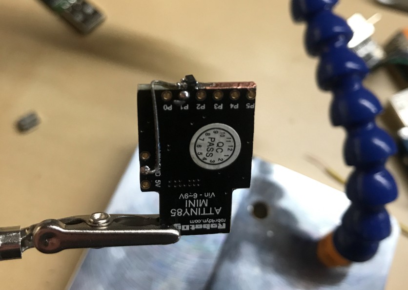
In searching for the least expensive source that didn’t take months to arrive from China, I realized that the $5 DigiSpark was a nearly prebuilt board and I could get them on Amazon. There are also several DigiSpark clones on Amazon for ~$3 and down to $1.50 on eBay. Not only did the $3 DigiSpark clone have the ATtiny85 I wanted, but it had most of the other components I needed.
Essential parts:
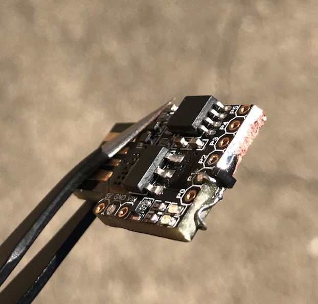
Now, if you want to cram everything into the little USB thumb drive, you’ll need to shrink things down. A DigiSpark is too big. I did this by cannibalizing the DigiSpark. At the time, this ended up being more cost effective (and faster to acquire) than sourcing all the components individually. The following information assumes you are choosing cannibalization.
Circuit:
The basics of this design use the V-USB reference schematic, and add a MOSFET to pin 5. The circuit is extremely basic and the bare minimum for sane USB functionality.
WARNING:
- The resistor between the Source and Drain of the MOSFET still needs exploration, especially if any alternate components are used. If the resistance is too high, or there is no resistor at all, the payload will momentarily trigger on boot. If the pins of the ATtiny are powered up on boot, it will also trigger. Thanks to Graham Sutherland (@gsuberland on twitter) for the help here.
When using the ATtiny from a DigiSpark, programming is very easy as there is already a bootloader. You open up your Arduino IDE, create a sketch, tell the sketch to upload, then plug in the board to your USB port.
If you are running this on an uncannibalized DigiSpark, there is a blue LED that also turns on when pin 5 sends power. This is very helpful for testing.
Below is the sketch used in the original video with the confetti. The OS X Terminal is opened, then the volume is turned up and a fullscreen browser pointed at a vimeo video is launched. (Animation is by RedNoseStudio) It’s a pretty basic payload by HID attack standards. After a 22 second delay, I use digitalWrite to send voltage to the MOSFET. After 3 seconds, voltage is removed for this specific payload.
#include “DigiKeyboard.h”
#define KEY_TAB 43
#define KEY_DOWN 81
#define KEY_DELETE 42
#define KEY_PRINTSCREEN 70
#define KEY_SCROLLLOCK 71
#define KEY_INSERT 73
#define KEY_PAUSE 72
#define KEY_HOME 74
#define KEY_PAGEUP 75
#define KEY_END 77
#define KEY_PAGEDOWN 78
#define KEY_RIGHTARROW 79
#define KEY_RIGHT 79
#define KEY_DOWNARROW 81
#define KEY_LEFTARROW 80
#define KEY_UP 82
#define KEY_UPARROW 82
#define KEY_NUMLOCK 83
#define KEY_CAPSLOCK 57
#define KEY_MENU 118
void setup() {
 pinMode(1, OUTPUT);
 pinMode(0, OUTPUT);
 digitalWrite(0, LOW);
 digitalWrite(1, LOW);
 DigiKeyboard.sendKeyStroke(KEY_SPACE, MOD_GUI_LEFT);
 DigiKeyboard.delay(500);
 DigiKeyboard.sendKeyStroke(0);
 DigiKeyboard.println(“terminal”);
 DigiKeyboard.delay(50);
 DigiKeyboard.sendKeyStroke(0);
 DigiKeyboard.sendKeyStroke(KEY_ENTER);
 DigiKeyboard.delay(1500);
 DigiKeyboard.sendKeyStroke(0);
 DigiKeyboard.println(“osascript -e ‘set volume 4’ && open https://player.vimeo.com/video/184549201?autoplay=1");
 DigiKeyboard.sendKeyStroke(0);
 DigiKeyboard.delay(22000);
 DigiKeyboard.sendKeyStroke(0);
 digitalWrite(0, HIGH);
 digitalWrite(1, HIGH);
 DigiKeyboard.delay(3000);
 digitalWrite(0, LOW);
 digitalWrite(1, LOW);
}
void loop() {
}
- legit PCB for ease of soldering
I didn’t document every step of the way, but there were some notable failures.
A DigiSpark with MOSFET:


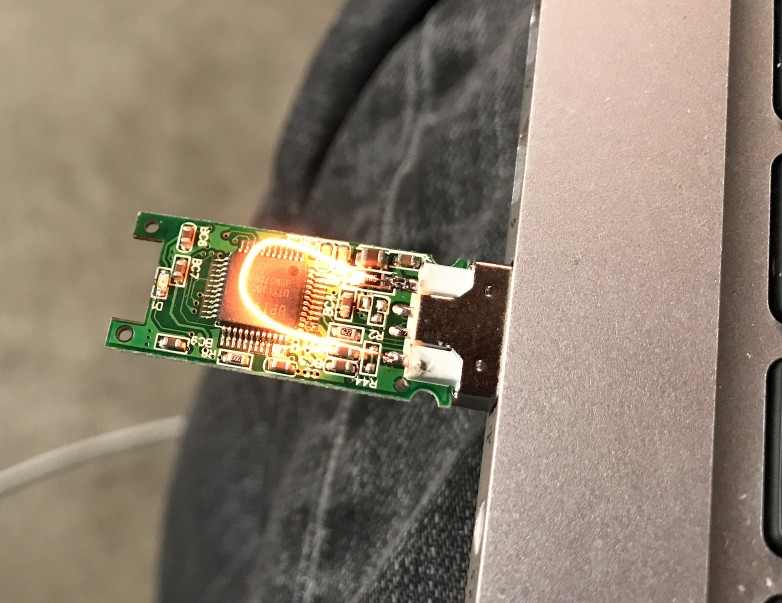
the initial 5v trigger test:
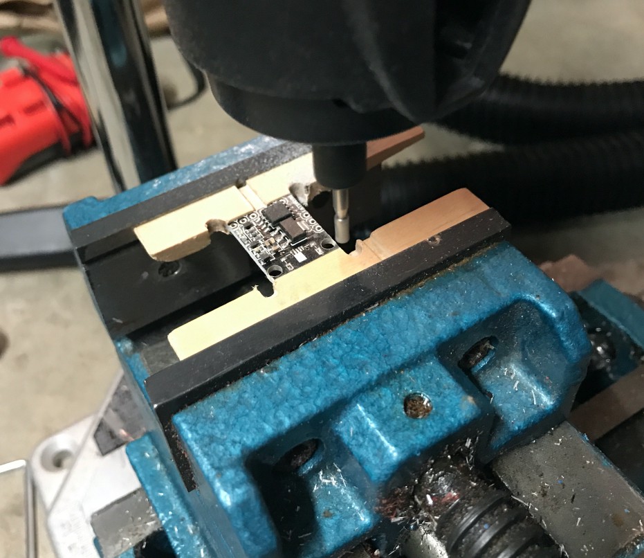
Trying to shave down the size of a DigiSpark in hopes of it fitting in a clamshell case (totally didn’t go small enough):
